
Flowchart
Plan lector de electronica

Flowchart content
Digital Electronics
Digital logic is the foundation, not only of computing but also many other electronic devices and control systems found in almost every part of modern life. digital logic relies on only seven types of logic gates connected together with a minimum of additional components
logic gates
The principle of operation is that the circuit operates on just two voltage levels, called logic 0 and logic 1. Traditionally many logic circuits use 5V to represent logic 1 and 0V to represent logic 0 although in many modern circuits 1 and 0 are represented by 3.3V and 0V. When either of these voltage levels is applied to the inputs, the output of the gate responds by assuming a 1 or a 0 level, depending on the particular logic of the gate. The logic rules for each type of gate can be described in different ways, by a written description of the action, by a truth table, which is a table showing all the possible logic states at the inputs and output of the gate, or by a Boolean algebra statement.
The classification of logic gates are
NAND (Not AND)
NOR (Not OR)
XOR (Exclusive OR)
NOT.
OR
AND
XNOR (Exclusive NOR)

it's based on





The AND gate output is at logic 1 when, & only when all its inputs are at logic 1, otherwise the output is at logic 0.
• The OR gate output is ate logic 1 when one or more of its inputs are at logic 1. If all its inputs are at logic 1 , the output is at logic 0.
• The NAND gate output is at logic 0 when & only when all its inputs are at logic 1. Otherwise the output is at logic 0.
• The NOR gate output is at logic 0 when one or more of its inputs are at logic 1. If all of its inputs are at logic 0, the output is at logic 1.
• The XOR gate output is at logic 1 when and only one of its inputs is at logic 1. Otherwise the output is at logic 0.
The XNOR gate output is at logic 0 when one and only one of its inputs is at logic 1 Otherwise the output is at logic 1. (It is therefore similar to the XOR gate, but its output is inverted).
• The NOT gate output is at logic 0 when its only input is at logic 1, and at logic 1 when its only input is at logic 0. For this reason it is often called an INVERTER.
Boolean Statements
Boolean statements use letters from the beginning of the alphabet, such as A, B, C etc. to indicate inputs, and letters from the second half of the alphabet, very commonly X or Y and sometimes Q or P to label an output. The letters have no value meaning in themselves, they are just used to label the various points in the circuit. The letters are then linked by a symbol indicating the logical action of the gate.
The actions of the logic gates can be described as follows
Truth Tables
Another useful way to describe the action of a digital gate (or a whole digital circuit) is to use a truth table. Each table consists of two or more columns, one column for each input or output; the number of lines in the column will be enough to record all possible logic states for that input or output.
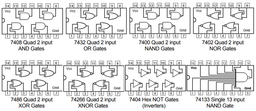
Logic ICs
Information
- Description
- Flowchart on Plan lector de electronica, created by johann padilla on 02/04/2022.
- Created by
- johann padilla
- Views
- 0
- Rating