
Transmission Gates
Slides in this set (5)
-
-
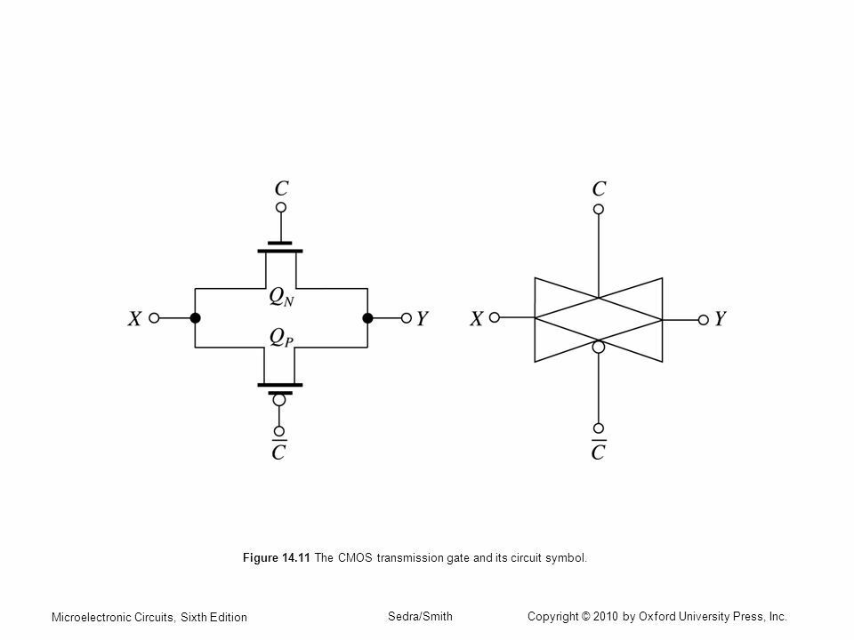
- A transmission gate is an idea where given an input:
- - If the gate is ON: input will be directly connected to output
- - If the gate is OFF: input is blocked from the output
- Therefore, acting as a switch!
- Why would we want transmission gates?
- - Multiplexing (Selecting)
- - Transistor logic
-
Components that act like a switch:
- NMOS
- - When gate voltage = 0V:
- - NMOS OFF, Output = 0V
- - GOOD, STRONG LOW 👍
- - When gate voltage = Vdd:
- - NMOS ON, Output = Vdd - Vtn
- - NOT GOOD, WEAK HIGH 👎
- PMOS
- - When gate voltage = Vdd : PMOS OFF -> Output = 0
- - When gate voltage = 0V, two scenarios:
- Input voltage = Vdd -> Output = Vdd 👍
- - STRONG HIGH
- Input voltage = 0V -> Output = Vt 👎
- - WEAK LOW
-
- We want the strong low from NMOS, while simultaneously having the strong low for PMOS, so what do we do?
- - Design a transmission gate where PMOS and NMOS are in parallel
- - IMPORTANT: the PMOS control signal must be inverted, so that both transistors will be on/off simultaneously
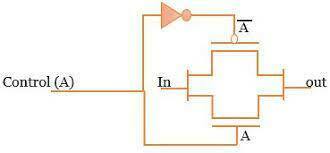
- Caption: Control signal (A) is inverted for the PMOS
-
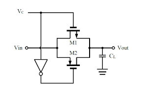
- - The total current charging the capacitor is the sum of the currents through the NMOS and PMOS
- - The PMOS enters triode region when the output voltage equals |Vtp|, but it continues to conduct until the capacitor is fully charged, and output reaches the high output voltage
- - ensures a "good 1"
- - When input voltage goes low, PMOS and NMOS switch roles
- - The NMOS will continue to conduct until the capacitor is fully discharged and output voltage reaches the low output voltage
- - ensures a "good 0"
- Caption: The presence of the PMOS device provides additional current, leading to a lower tPLH compared to a single NMOS switch configuration.
Information
- Description
- Undergraduate CSE 112 (Pass Transistor Logic) Slide Set on Transmission Gates, created by Ashley Hope Reynolds on 06/12/2023.
- Created by
- Ashley Hope Reynolds
- Views
- 1
- Rating