
Mind map
FILTER CIRCUIT
Map content
FILTER CIRCUIT
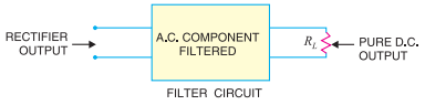
A filter circuit is a device which removes the a.c. component of rectifier output but allows the d.c. component to reach the load.
- filter circuit should be installed between the rectifier and the load
- A filter circuit is generally a combination of inductors (L) and capacitors (C)
- A capacitor passes a.c. readily but does not pass d.c. at all.
- An inductor opposes a.c. but allows d.c. to pass through it.
- Types of Filter circuits
- capacitor filter
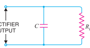
- It consists of a capacitor C placed across the rectifier output in parallel with load RL.
- It consists of a capacitor C placed across the rectifier output in parallel with load RL.
- choke input filter
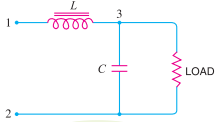
- It consists of a choke L connected in series with the rectifier output and a filter capacitor C across the load.
- It consists of a choke L connected in series with the rectifier output and a filter capacitor C across the load.
- capacitor input filter or π-filter
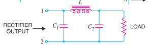
- It consists of a filter capacitor C1 connected across the rectifier output, a choke L in series andanother filter capacitor C2 connected across the load.
- It consists of a filter capacitor C1 connected across the rectifier output, a choke L in series andanother filter capacitor C2 connected across the load.
- capacitor filter
- A filter circuit is generally a combination of inductors (L) and capacitors (C)
- filter circuit should be installed between the rectifier and the load
Images and files in the map
Information
- Description
- ELECTRONICA ANALOGICA Mind Map on FILTER CIRCUIT, created by JOANA GARCIA on 02/03/2019.
- Created by
- JOANA GARCIA
- Views
- 0
- Rating