
Mind map
Chapter 3- Logic Circuits
Map content
Chapter 3- Logic Circuits
Logic Gates
- Take binary inputs and produce a binary output
- Control sensory electronic circuits
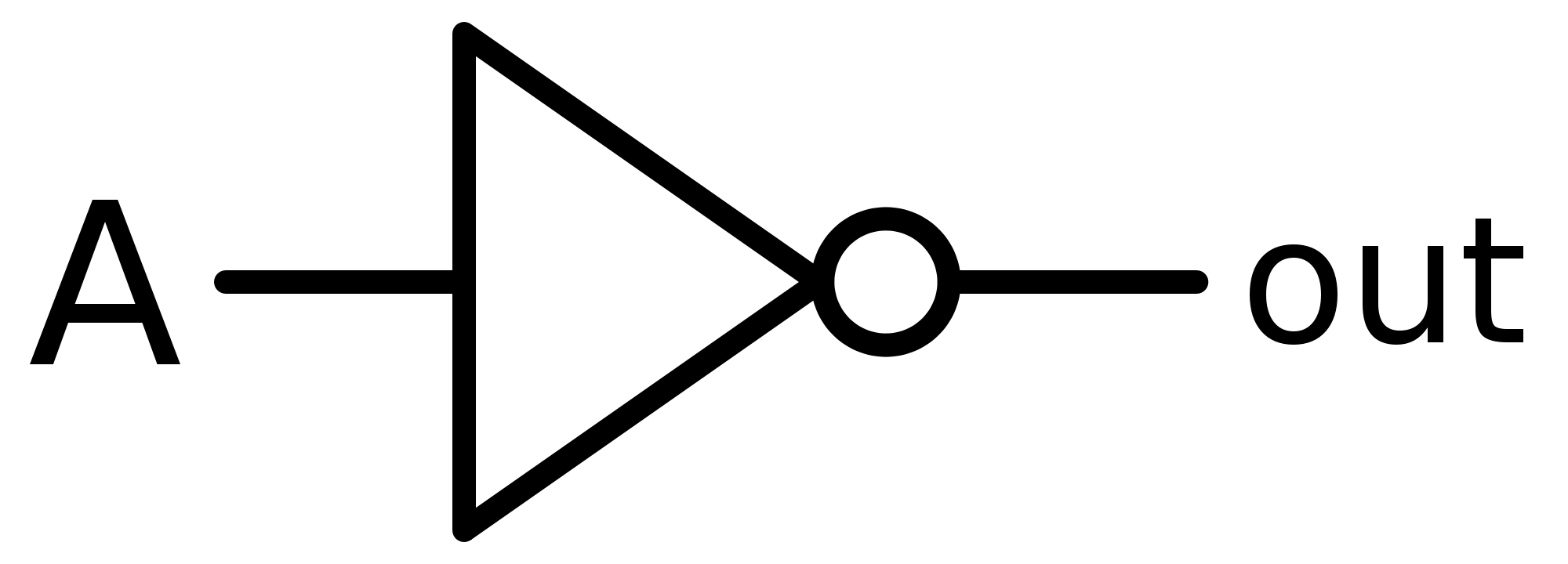
- NOT Gate
- Output is the opposite of the input
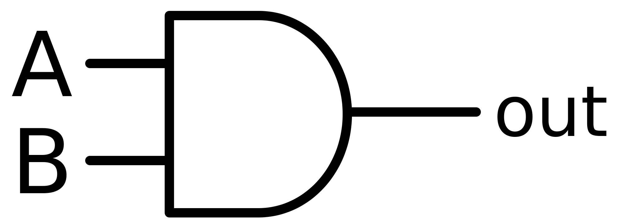
- AND Gate
- Output is 1 if both Inputs are 1
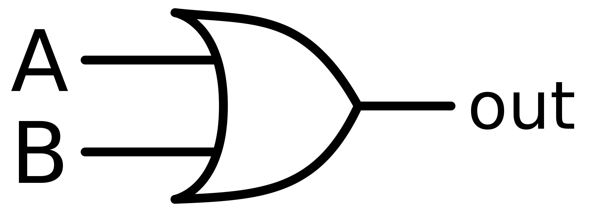
- OR Gate
- Output is 1 if either or both inputs are 1
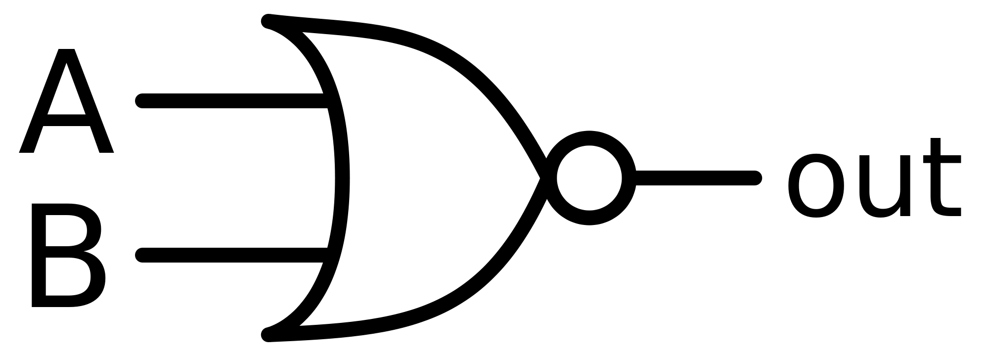
- NOR Gate
- Output is 1 if neither input is 1
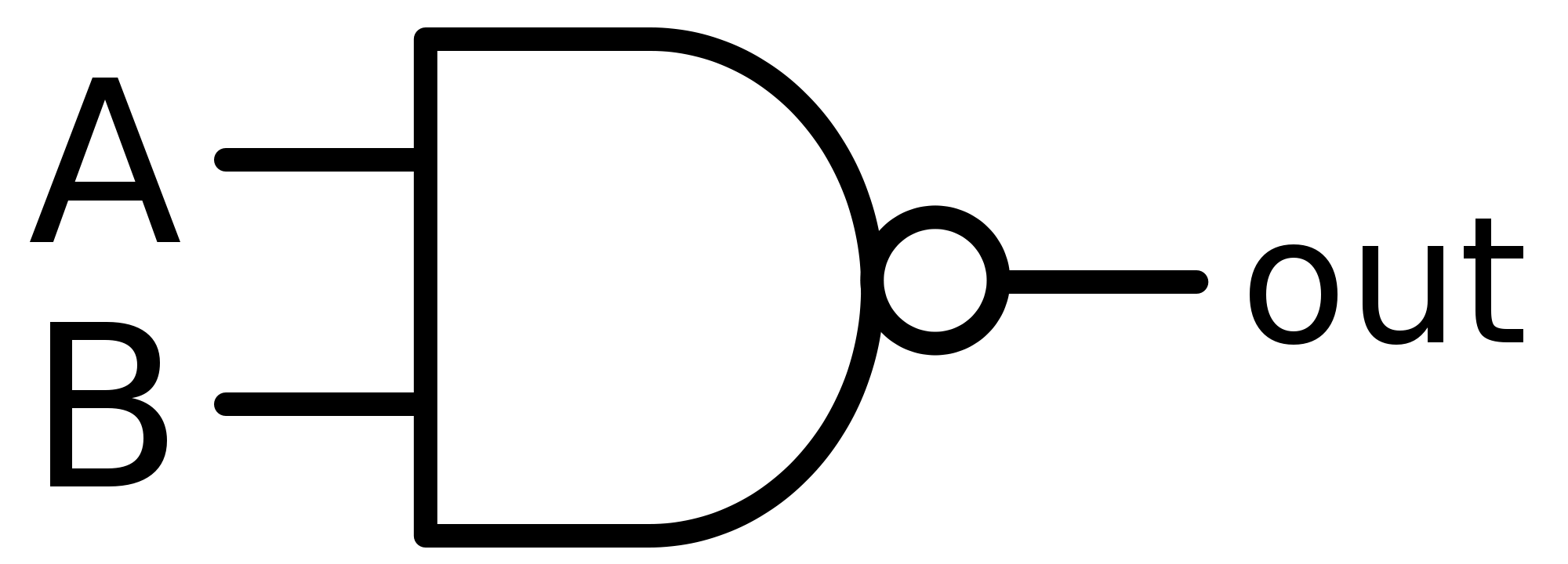
- NAND Gate
- Output is 1 if not both inputs are 1
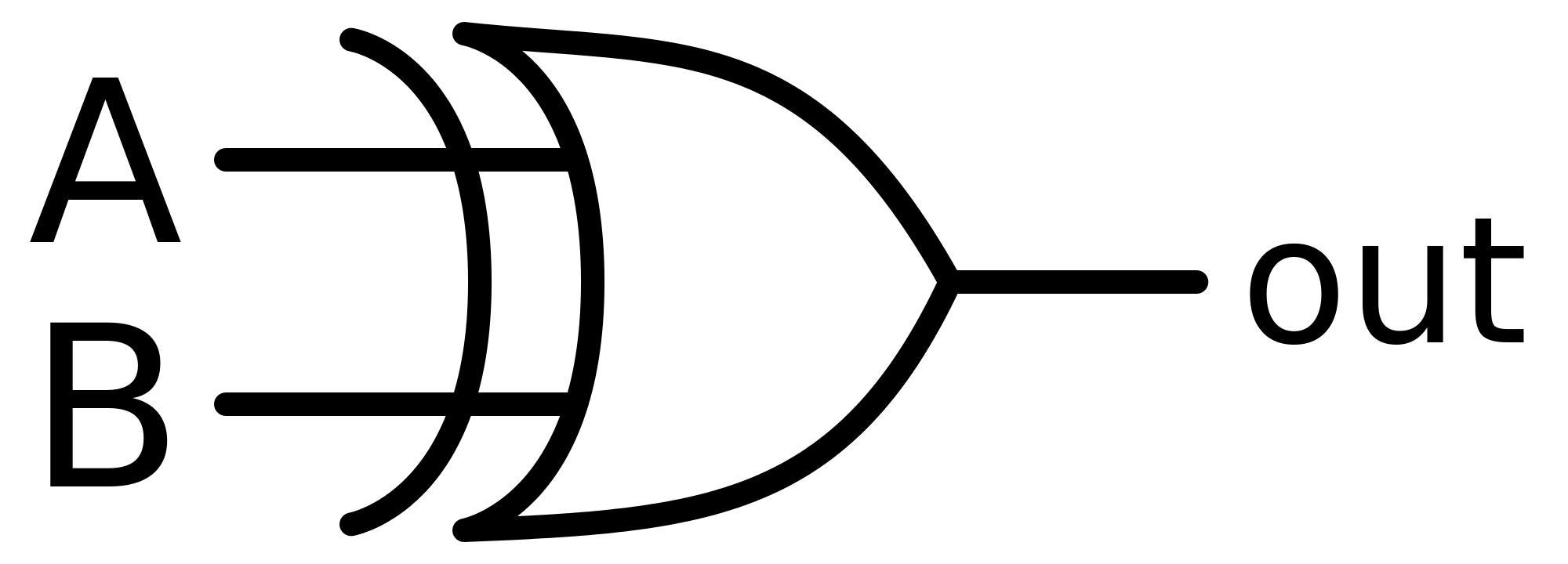
- XOR Gate
- Output is 1 if inputs are opposites
- Number of possible outputs is equal to 2^The number of inputs
- 1 input has 2 outputs
- 4 inputs has 16 outputs
- Take binary inputs and produce a binary output
Logic Circuits
- Several logic gates combine to create a logic circuit
- These circuits are designed to carry out specific functions
- Opening a window in a greenhouse depending on the humidity
- Turning off the lights in a house when the natural light intensity reaches a threshold value
- Conrolling a robot depending on the surroundings
- Turns on a heater if the temperature drops below a threshold value
- These circuits are designed to carry out specific functions
- Checking of the output from a logic circuit is done using a truth table
- Truth tables trace the output from a logic gate or circuit by listing all possible inputs
- Electronic circuits work on making decisions
- Need logic gates to make decisions based on inputs
- Several logic gates combine to create a logic circuit
Companies will decide between using
- Off the shelf logic gates and building up a circuit eg just using the NAND gate we could create the AND, OR and the NOT gate
- Simplifying the logic circuit by using more advanced gates eg using XOR, XAND and XOR gates to reduce size of the logic circuit
Use
- We can design a logic circuit given a logic statement
- Create the logic statement and then construct the circuit in parts and then create the truth table
- We can design a logic circuit to carry out a function
- Convert information given into logic statements, produce circuits and then produce the truth table
- Produce a truth table from a logic circuit
- Split the logic circuit into parts and follow the output from part 1 to the end and then create a truth table
- We can design a logic circuit given a logic statement
Images and files in the map
Information
- Description
- GCSE Computer Science Mind Map on Chapter 3- Logic Circuits, created by Yusuf Salim on 18/02/2017.
- Created by
- Yusuf Salim
- Views
- 0
- Rating