
Electronics Technician - Ongoing (diagrams/schematics I need to study)
Slides in this set (8)
-
- Caption: woah
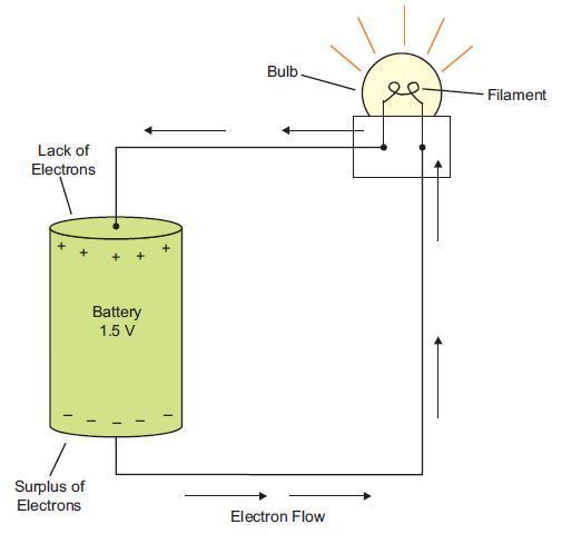
- Electron flow theory is shown here. Remember that a direct current is the continual flow of electrons in the same direction. A common source of direct current is a battery. In the circuit illustrated here, electrons move from the negative (-) battery terminal, through the lightbulb, and back to the positive (+) terminal.
-
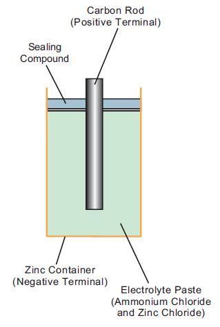
- A dry cell battery is composed of a zinc shell filled with a chemical paste called electrolyte. A carbon rod is then inserted into the paste. As a result, a chemical reaction occurs within the battery, and a lack of electrons develops at the carbon rod. The rod therefore becomes the positive terminal and is labeled with a positive (+) sign. At the same time in the battery, a surplus of electrons develops in the zinc shell. The shell then becomes the negative terminal and is labeled with a negative (-) sign.
-
Comparing Electricity with Water
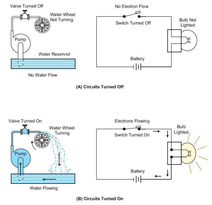
- Caption: Would you look at that! A water system looks just like an electric circuit.
-
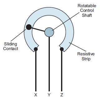
- Caption: The major parts of a potentiometer include a resistive strip, a sliding contact, and a rotating shaft.
-
Basic Component's Schematic Symbols
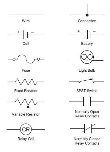
- Caption: Here are some of the standard symbols used to indicate electrical components in schematic diagrams.
-
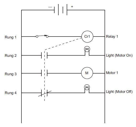
- Caption: In this relay circuit, the contacts of the relay will change when the coil of the relay is energized.
- This type of diagram is called a relay ladder logic diagram. This is because the diagram looks like a ladder with rails and rungs.
- Note that the two vertical "rails" are connected to the power source. The horizontal "rungs" contain the switches, coils, and loads for the circuit. The rungs are actually simple series circuits that are connected between the power rails and controlled by one relay contact on each rail.
-
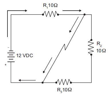
- In this illustration, current flows through the first resistor (R1), and then short circuits, bypassing the second and third resistors (R2 and R3). This greatly increases the current in the circuit.
- Caption: intense
-
Potentiometer & Rheostat Anatomy
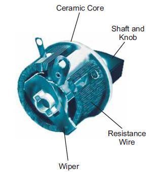
- Caption: High-power Rheostat Back View
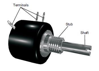
- Caption: Main External Parts of a Potentiometer
Information
- Description
- I present to you some interesting slides I made from the diagrams, pictures etc. from the course I'm taking at Penn Foster.
- Created by
- That Yeti Dog Person
- Views
- 45
- Tags
- Rating