
Flashcards
Week 2
Cards in this deck (31)
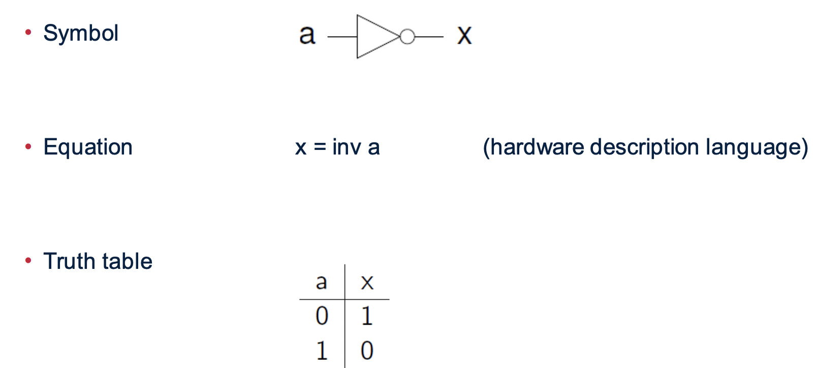
- 14 Logic Gatesinv, and2, or2, xor2
- 2Flip flopsdff (delay flip flop
- 3Digital circuitsAre built from a very small number of primitive little elements
They are hardware - 4InverterThe output is the logical opposite of the input
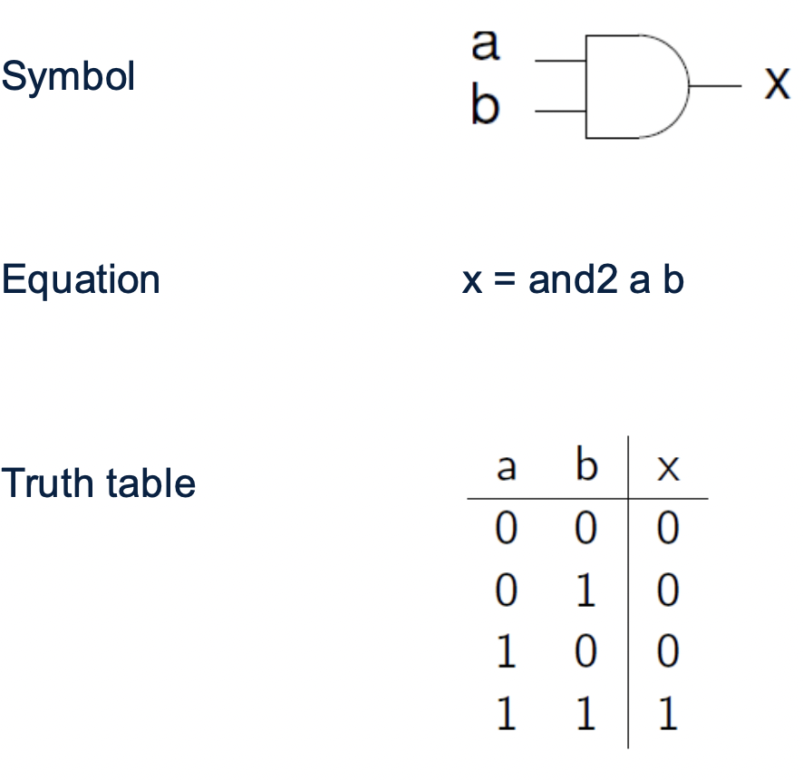
- 52-input and gateThe output is 1 if all inputs are 1
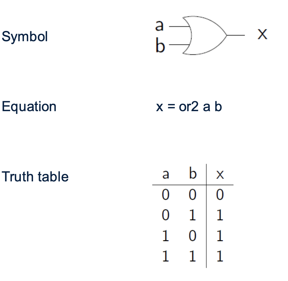
- 62-input inclusive or gateThe output is 1 if any input is 1
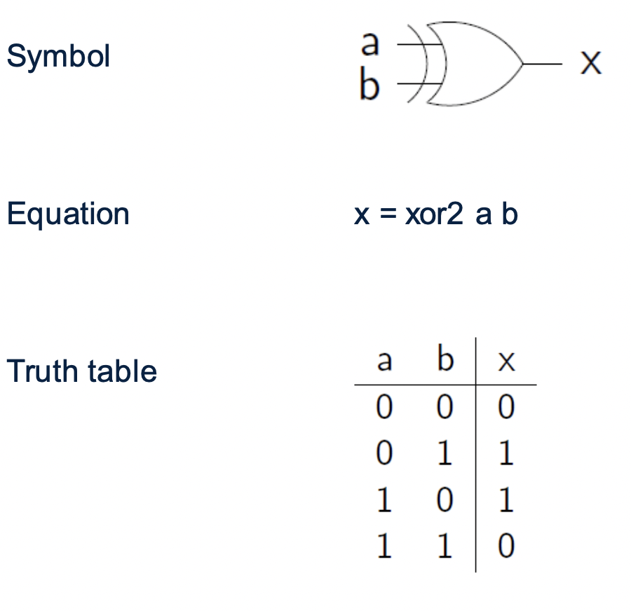
- 72-input exclusive or gateThe output is 1 if either input is 1, but not both
- 8Gate delayIf an input changes at a point in time, it will take the logic gate a small amount of time to bring the output to the new value: the gate delay
Gate delays are on the order of 0.01 ns (ns = nanosecond, 1 s = 109 ns)
May be faster or slower, depending on the transistor technology used
– TTL, CMOS, etc - 9inputs remain stablethe output remains stable
- 10Combinational circuitsA combinational circuit is a digital circuit that
– Consists of logic gates connected together
– Has some inputs and produces some outputs
– Contains no feedback loops
– The outputs depend on the input values (i.e. the circuit has no memory) - 11Circuit simulation– You're given the inputs to a circuit
– You calculate what its outputs should be, by doing the same calculations
the hardware would make
“execute a program by hand” - 12How to simulate a combinational circuit1. You're given the inputs to the circuit
– The other signal values are unknown (internal, output)
2. Find an output of a logic gate where all the inputs are known, and write
down the output value
– Using the truth table for the logic gate
3. Repeat until all signals are known - 13Building block circuitsThe solution is abstraction
– We will put several components together to build a black box circuit
– Then several of those will combine to make a bigger one
– And then a still-larger one… - 14MultiplexerThe multiplexer is the fundamental circuit used to make decisions is a hardware version of the if-then-else expression
– Given three inputs: c, x, y
– Produces one output
• If c = 0 the output is x
• If c = 1 the output is y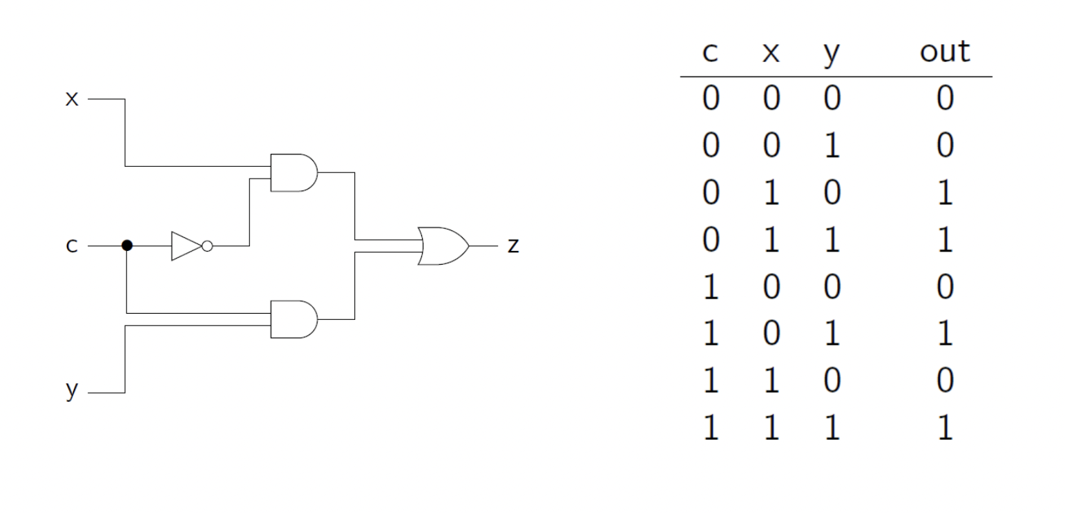
- 15Multiplexers are importantMultiplexers are a central black box which we will use again and again
Most conditional operations in digital circuits are implemented, at the lowest
level, by a multiplexer
In a circuit, we don’t execute “if-then-else statements”, there are no
statements!
Instead, we define signals using “if-then-else expressions”, implemented
with multiplexers - 16Complex computing from simple logic gatesYou can understand completely what each of them does
So they can’t do more complex things like…
– Arithmetic, execute statements, make decisions, etc
Then… how can a (complex system like a) computer work?
– The complex behaviour emerges from the interaction of the simple parts - 17Elementary algebraElementary algebra is about properties of operations on numbers: + - x ÷
Helps you solve many problems involving numbers
There are many different algebras, for different kinds of object - 18Constants and operations of Boolean algebraThere are two values: 0, 1
We can use variables to stand for a value: x, y, z, …
There are three operators that correspond exactly to a logic gate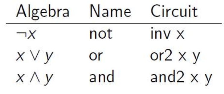
- 19Definition of the operationsThe same as the definitions of the logic gates
– Except we don’t have a Boolean operator for the “exclusive or” gate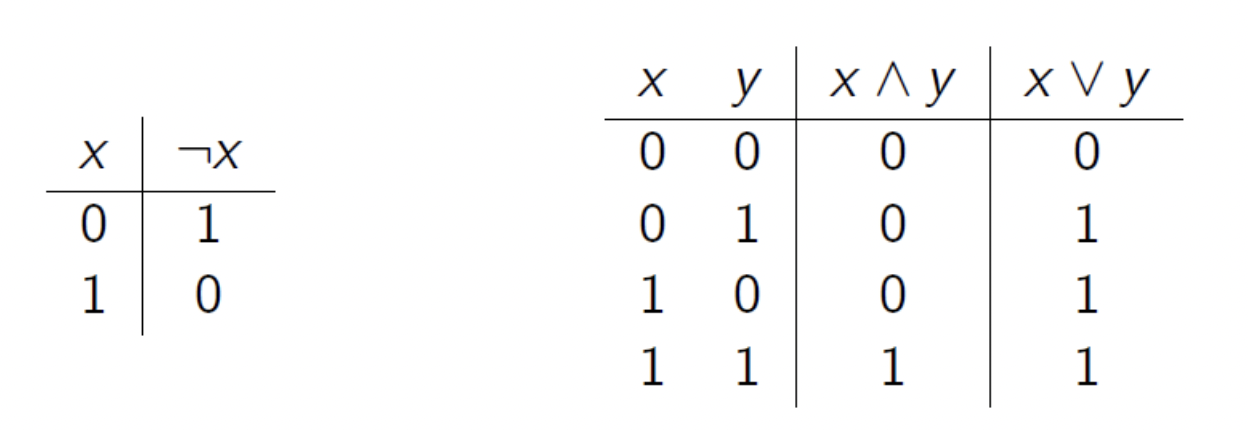
- 20Laws of Boolean algebraThe basic rules (or axioms, etc) describing logical operations
You can use these to reason about circuits
– Simplify expressions
– Calculate signal values (e.g. the multiplexer)
– Prove that two circuits calculate the same value
– Derive circuits to meet a specification
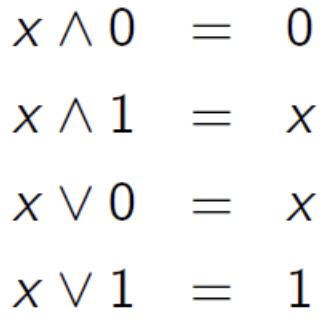
– … - 21Operations with constants
- 22IdempotenceAn operation is idempotent if doing it several times is the same as once
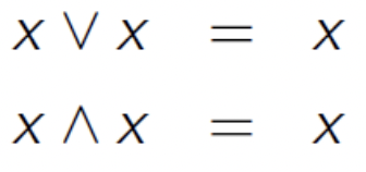
- 23CommutativityYou can swap around the order of inputs to an and-gate or an or-gate
without changing the result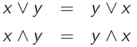
- 24AssociativityGives a way to compute the logical and/or of many inputs, by using several
2-input and/or gates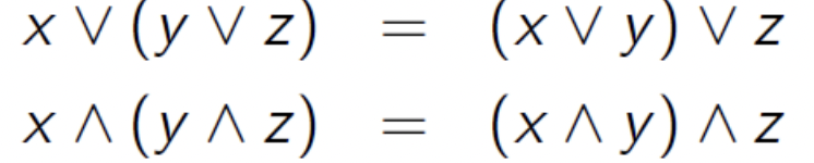
- 25Distributive and absorption laws
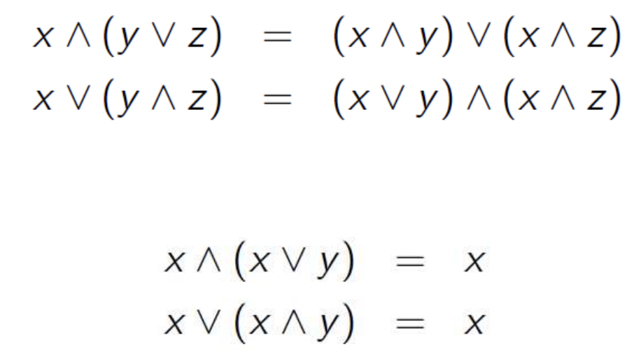
- 26Half AdderAdds two bits
– Since the result could be 0, 1, or 2, we need a two-bit representation of
the sum, called (carry, sum)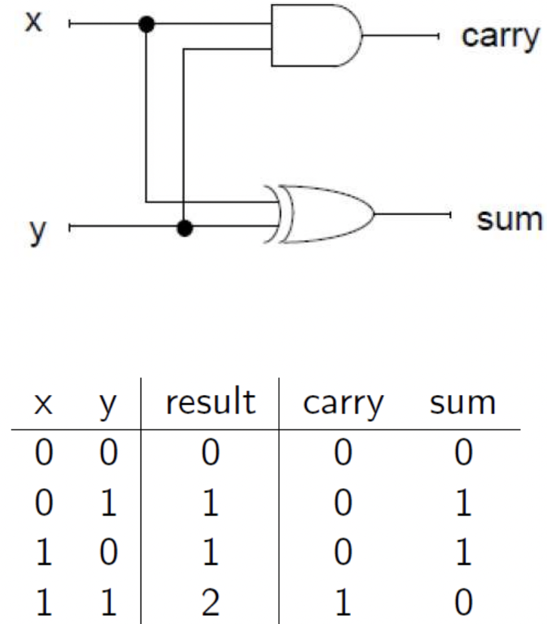
- 27Full AdderTo add two binary numbers, we must add three bits for each column
– The two data bits (one from each word)
– The carry input from the column to the right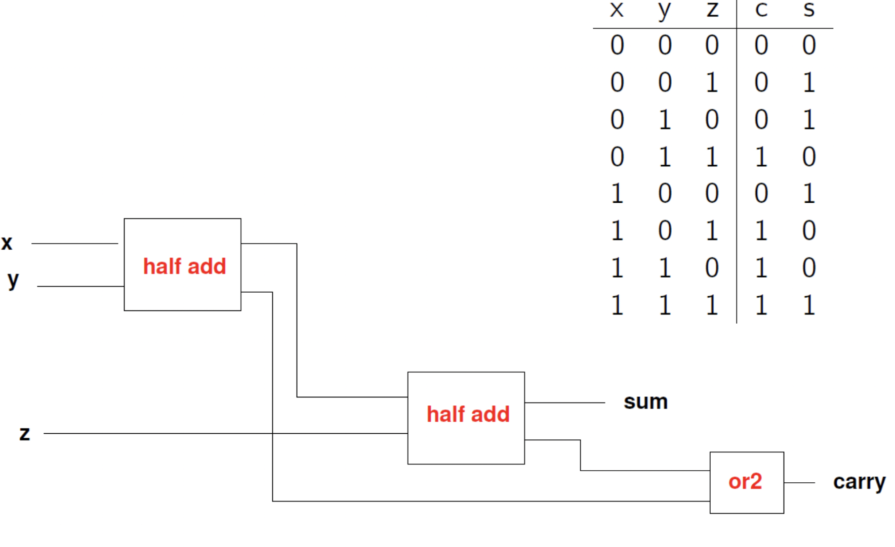
- 28Binary word additionUse a full adder circuit for each bit position
– A bit from x and a bit from y
– The carry output from the full adder to the right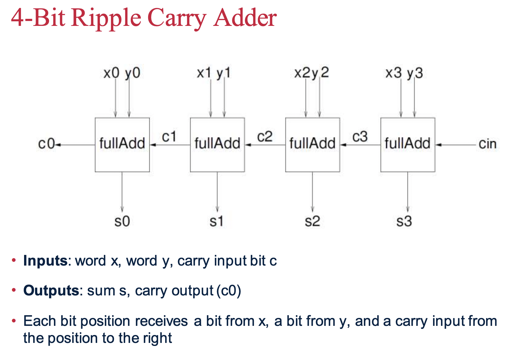
- 29Subtraction• Work with two's complement numbers
• Note that x - y = x + (-y)
• Recall that to negate a number, you invert the bits and add 1
– To invert the bits of y, just put an inverter on each bit of y
– To add 1, just set the carry input to the entire ripple carry adder to 1
• Solution: use a ripple carry adder, with each bit of y inverted, and with carry
input = 1, and the output will be x - y - 30schematic capture– You draw the circuit interactively
– A diagram of a circuit is called a schematic diagram
– The software then simulates it - 31schematic diagramA diagram of a circuit is called a schematic diagram
Information
- Description
- Computer Science Flashcards on Week 2, created by Isaac Gilbert on 18/01/2022.
- Created by
- Isaac Gilbert
- Views
- 0
- Rating