
Mind map
Digital Electronic Design
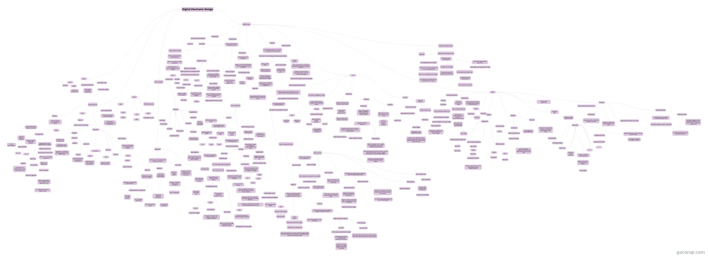
Mind map: Digital electronic design
Map content
Digital Electronic Design
Number Systems
- Boolean
- Binary numbers (represent discrete values)
- Types
- Signed (representing negative numbers)
- Sign and magnitude notation
- Sign bit (first bit)
- 0 is +ve
- 1 is -ve
- 0 has 2 representations
- Sign bit (first bit)
- 2's complement
- Weighting of the most significant bit is negative
- Weights at powers of 2
- Need to know amount of bits
- Only one zero, so range is asymetrical
- Need to know amount of bits
- Weights at powers of 2
- Operations
- From 4 to 8 bit
- Extend the signed bit
- Addition and Subtraction
- Same as unsigned
- Works treating both as 2's complement and ignoring the carry
- For subtraction, easier to negate and add
- Works treating both as 2's complement and ignoring the carry
- Same as unsigned
- Negation
- Complement the number, add one to the result, discard carry
- From 4 to 8 bit
- Hardware may be shared with unsigned
- Overflow (carry for signed no's)
- An indication that something is broken
- Should be no overflow if adding complements that differ in sign
- An indication that something is broken
- Weighting of the most significant bit is negative
- Sign and magnitude notation
- Unsigned
- Operations
- Addition
- Subtraction
- Operations
- Signed (representing negative numbers)
- Types
- Binary numbers (represent discrete values)
- Conversions
- Decimal to
- Binary
- Divide whole part by 2, and multiply fraction by 2
- Base 7
- Divide whole part by 7, multiply fraction by 7
- Binary
- Binary to
- Hex
- Group in 4's from RHS and convert
- Decimal
- Hex
- Hex to
- Binary
- Convert each 4 bit
- Binary
- BCD to Decimal
- Group in 4's from right and convert like unsigned
- Decimal to
- Hex
- Base 16
- Easy to convert and compact
- Base 16
- Binary coded decimal
- 4 bit code represents each decimal digit
- Input/output conversion easier but less efficient
- 4 bit code represents each decimal digit
- Boolean
Basics
- Data
- Analogue
- Digital
- Prescision limited by bits
- Intergrated circuits (ICs)
- Made digital processing inexpensive
- Unit distance code
- Only one bit changes
- Data
Digital Circuits
- Combinational
- Output purely function of input (no state)
- Multiplexers (mux)
- Made up of many gates
- Digital equivalent of a multiway switch
- For 2^N inputs need N selection lines
- 2 to 1
- 1 selection line
- 4 bit wide
- Busses
- 4 to 1
- 2 selection lines
- 8 to 1
- 3 selection lines
- 2 to 1
- For 2^N inputs need N selection lines
- Digital equivalent of a multiway switch
- Function implementation
- Using programmable tied inputs, any function can be made
- Three variables
- Can get a wider range of functions by adding an inverter
- Left most bits go to S1,S0 and then the third bit is the inverted
- Outputs divided into pairs of rows
- Left most bits go to S1,S0 and then the third bit is the inverted
- Can get a wider range of functions by adding an inverter
- Three variables
- Using programmable tied inputs, any function can be made
- Made up of many gates
- Decoders (demux)
- 1 input multiple outputs
- e.g priority encoder : gives most significant bit
- 1 input multiple outputs
- 3 State buffers (Tristate)
- To share a signal between multiple sources
- When en=0, output is Z (high impedence)
- Not being driven, is unknown, switch open and floating
- When en=0, output is Z (high impedence)
- To share a signal between multiple sources
- 3 State busses
- 2, 3 state gates and a shared bus
- Allows to share a signal between 2 different sources, forming a multiplexer
- The high output drives
- If both 0 : floating
- If both high: damage
- The high output drives
- Allows to share a signal between 2 different sources, forming a multiplexer
- 2, 3 state gates and a shared bus
- Multiplexers (mux)
- Output purely function of input (no state)
- Sequential
- Output dependent on previous events and current inputs (has state)
- Memory Elements
- Latches
- Minimal 2 stable state system
- Set-reset latch (must know original state)
- S&R both high is not allowed
- Possible states
- Set
- Reset
- Hold
- Characteristic table
- Can be used to remove bounce
- Weak keeper circuit (poor mans debounce)
- Keeps wire from floating
- Weak keeper circuit (poor mans debounce)
- Gated/ Transparent Latch
- If gate=1 D goes through to Q
- Awake all the time
- Disadvantage: output can change at anytime while gate is active
- Once gate=0, latches on to last value (hold)
- Awake all the time
- If gate=1 D goes through to Q
- Flip flops
- Edge triggering
- Only respond to values at their clocked inputs on a clock transition
- Have a clock
- Tolerant of hazards (part of timing set up)
- D Type Flip Flop
- On a clock edge D goes through to Q
- Can only set and reset
- On a clock edge D goes through to Q
- J-K flip flop
- The clocked equivalent of an SR, but when both inputs are high the FF toggles
- Set
- Reset
- Hold
- Toggle
- JK-FF Symettry
- The clocked equivalent of an SR, but when both inputs are high the FF toggles
- Toggle flip flop
- Toggle when single input is active else hold
- Good for counting circuits
- Toggle when single input is active else hold
- Timing requirments
- Data has to be valid around the clock edge for correct operation
- Set up and hold times
- Still a propogation delays (for asynchronous inputs and clock input to outputs)
- Minimum time b/w consecutive clock edges determined by round trip delay
- Frequency needs to be less than the corresponding frequency for tmin
- e.g 3 bit ripple counter
- Delays add up (skewed outputs)
- Due to asynchronous outputs
- Delays add up (skewed outputs)
- Minimum time b/w consecutive clock edges determined by round trip delay
- Still a propogation delays (for asynchronous inputs and clock input to outputs)
- Set up and hold times
- Data has to be valid around the clock edge for correct operation
- Edge triggering
- Latches
- Types of sequential circuits
- Registers
- Collection of flip flops with a common clock working together (treated as a unit)
- Counters
- A device that counts by transitioning through a sequence of states
- Determine sequence by next state table
- Design of arbitrary sequence
- Draw STD
- Enter sequence information into table
- Add flip flop information into table using appropriate excitation
- Determine FF input equations and circuit (using k maps where necessary)
- Add flip flop information into table using appropriate excitation
- Enter sequence information into table
- If extra flip flops
- Use don't cares
- Check later their values and for unsafe circuitry from their states (also applies to state machines)
- Use don't cares
- Draw STD
- A device that counts by transitioning through a sequence of states
- Shift register
- Values move either left or right
- Usually serial in/ parralel out
- Serial communication : Use two connected registers with a common clock to keep in parralel or serial (transmitted between in the opposite type)
- Usually serial in/ parralel out
- Values move either left or right
- RTL
- Requires 3 state outputs
- e.g accumulator
- Requires 3 state outputs
- Counters
- Collection of flip flops with a common clock working together (treated as a unit)
- State machines
- Box that behaves differently according to what has happened previously
- Mealy state machine
- Moore state machine
- Outputs only depend on the current state of the machine
- Slower to react (on next clock edge), but reliable with clean transitions
- Needs extra state for output
- Slower to react (on next clock edge), but reliable with clean transitions
- In state table the output will not change within s state (2 rows)
- Outputs only depend on the current state of the machine
- Output can change at any time as the outputs are directly connected to the inputs
- Sometimes makes false predictions but can react quicker
- Moore state machine
- Mealy state machine
- State diagrams
- Appropriate legends
- Every possible transition must be covered
- Exhaustive and exclusive
- State machine chart
- State conventions
- Need to make arbitrary state assignments
- Binary encoding
- Hot one encoding
- State reduction
- Need to prove non equivalence to simplify
- For two equivalent states
- Outputs are equivalent
- Next transitions lead to equivalent states
- For two equivalent states
- Two state machines can also be equivalent in a similar way
- Need to prove non equivalence to simplify
- Box that behaves differently according to what has happened previously
- Registers
- Memory Elements
- Output dependent on previous events and current inputs (has state)
- I/O
- Gate delays (Propagation Delays)
- Delays between input changes and corresponding output
- Type
- Low to high (tplh)
- High to low (tphl)
- I/O levels
- Driving and driven gates
- Noise margin for reliable operation
- Voh> Vih
- Vol < Vil
- Compatability checked at limit conditions
- Noise margin for reliable operation
- Driving and driven gates
- Usually about 10 ns
- Type
- Delays between input changes and corresponding output
- CMOS Gates
- Rails to ground and Vdd (Pulls up or pulls down)
- Often with a totem pole output inverter
- Never on at the same time else shortcircuit
- Often with a totem pole output inverter
- Switching
- Current flow
- High current spikes caused by different paths for low/high output driving
- Bypass/Decoupling Capacitors
- Shortens effective path for current spikes (Used to filter noise on the power supply)
- Small capacitor close to IC
- Larger capacitor centrally
- Ground bounce
- When the outputs of an IC switch low producing a current spike through the ground leads
- The internal ground level of the IC then rises, this may be incorrectly be seen as a negative transistion for a currently high outptut
- Made better by slower fall/rise times and skew rate limited outputs
- The internal ground level of the IC then rises, this may be incorrectly be seen as a negative transistion for a currently high outptut
- When the outputs of an IC switch low producing a current spike through the ground leads
- Shortens effective path for current spikes (Used to filter noise on the power supply)
- Bypass/Decoupling Capacitors
- High current spikes caused by different paths for low/high output driving
- I/0 Switch
- When closed : Vo is high, when open Vo is low
- Resistor chosen for current required
- Switch bounce (mechanical)
- Causes noise
- Debouncing
- Schmitt trigger
- Designed for clean output transmission
- Using V+ and V- (both b/w Vih and Vil) as thresholds can create nearly a square waveform for a slow moving input with noise
- Designed for clean output transmission
- Debouncing circuit
- Add resistor, capacitor and replace inverter with schmitt trigger
- Schmitt trigger
- When closed : Vo is high, when open Vo is low
- Current flow
- Rails to ground and Vdd (Pulls up or pulls down)
- I/O LED
- Diode and inverter
- Vi low means LED off
- Vi high means LED on
- Diode and inverter
- Open drain gate (open collector)
- Only a pull down device present (seen as a switch), with an external pull up resistor
- Circuit pulls down hard and has slow rise
- Less likely to blow up if shorted to ground
- Also allows us to do logic on the wire
- Less likely to blow up if shorted to ground
- Circuit pulls down hard and has slow rise
- Only a pull down device present (seen as a switch), with an external pull up resistor
- Gate delays (Propagation Delays)
- Hazards
- An unexpected change in the output not implied by the logic design
- Occurs due to non ideal aspects of logic implementation
- Static 1 Hazard (SOP)
- Output should stay 1 but briefly goes 0
- Occurs in physical circuit due to 2 paths having different lengths
- Will only have a transition hazard going one way (inspection)
- Occurs in physical circuit due to 2 paths having different lengths
- Output should stay 1 but briefly goes 0
- Static 0 Hazard (POS)
- Output should stay 0 but briefly goes 1
- Hazard cover
- Add a redundant (non essential) grouping that covers the hazardous transition
- Adding an input that stays constant while the other two inputs are changing
- Only if we have physical control of our gates
- Adding an input that stays constant while the other two inputs are changing
- Add a redundant (non essential) grouping that covers the hazardous transition
- Static 1 Hazard (SOP)
- Occurs due to non ideal aspects of logic implementation
- Dynamic hazards
- An unexpected change in the output not implied by the logic design
- Programmable logic devices
- Dependant on pricing and need
- Cell based
- Array based (semi customisable)
- PAL (programmable array logic)
- Implements a sum of products but is one time programmable
- Each line is an AND gate with 4 inputs
- Can implement any SOP with up to 6 products from 4 inputs
- Each line is an AND gate with 4 inputs
- Implements a sum of products but is one time programmable
- GAL (generic array logic)
- A fixed OR array with a programmable AND array
- PLA (programmable logic array)
- Programmable AND and OR arrays
- CPLD (contains many PLAs)
- Programmable AND and OR arrays
- FGPA (field programmable logic array)
- Much larger and more general the CPLD
- PAL (programmable array logic)
- Dependant on pricing and need
- VHDL
- Levels
- Structural
- Behavioural
- Data flow
- Modules
- Entity (interface)
- Ports
- Architecture
- May be more than one
- Processes and logic
- May be more than one
- Top level
- Architecture: Instantiating modules and defining relationships between them
- Port mapping in entity (outer box)
- Entity (interface)
- Signals
- Assignments
- Delta delays
- Conditional signal assignments
- when/else
- Has priority
- when/else
- Within processes
- if/elsif
- Has priority
- Case
- No priority
- Each unique signal assignment within a clock edge statement build s a flip flop
- if/elsif
- Selected signal assignment
- with s select
- '' when ''
- No priority
- A packaged truth table
- For when others, feed in X's if it should never have an unexpected value
- A packaged truth table
- No priority
- '' when ''
- with s select
- Assignments
- Standard logic
- Represents larger range of values
- Logic levels
- U (uninitialised)
- X (forcing unknown)
- - (don't care)
- W (weakly driven unknown)
- Z (3 state, undriven, high impedence)
- Often need an else 'z' clause for 3 state buffers
- Z is very weak
- Often need an else 'z' clause for 3 state buffers
- 0
- 1
- H (weakly driven high)
- L (weakly driven low)
- Resolution function (if more than one gate is driving)
- U strongest, Z weakest, X trumps 1's and 0's
- Logic levels
- Represents larger range of values
- Has cocurrent statements
- Processes
- Sequential but executes in zero time
- Sensitivity list
- Will wake up when sensitivities change and execute
- Changes to signals don't occur till a delta time later
- Unintended latches
- If unspecified, a wire is kept at it's old value using a latch
- But latches capture hazards : undesirable
- Imply hole in logic
- Fix by setting default values at the top of a process
- Two paths through an entire cocurrent statement, one which assigns to a signal and one does not
- If unspecified, a wire is kept at it's old value using a latch
- How we build synchronous circuits
- Design considerations
- Clocking
- Clock skew
- Clock is delayed at different FF's
- Use clock enable to slow down
- But can't change ce too close to edge
- Use clock enable to slow down
- Clock is delayed at different FF's
- Clock skew
- Metastability
- If set up and hold times are not satisfied there could be an undecided value
- Or due to asynchronous inputs
- Worse at high frequencies
- Fix with input synchronisers (even multiple) for asynchronous output
- AS FF's don't act on values until next clock edge
- Fix with input synchronisers (even multiple) for asynchronous output
- Worse at high frequencies
- Clocking
- Levels
- Logic Polarity
- Tells how the circuit behaves
- Active low
- Active high
- Tells how the circuit behaves
- Combinational
Boolean Algebra
- Gates
- NOT
- AND
- NAND
- OR
- NOR
- XOR
- Controllable inverter
- XNOR (equivalence)
- Theorems
- Indemponent
- Involution
- Complementation
- Commutative
- Associative
- Distributive
- Used in converting POS to SOP
- Simplification
- Demorgan's
- Implementation for SOP and POS
- Consensus
- Sum of products
- ANDed variables ORed together
- Not unique
- Canonical form: each sum contains all variables
- Unique
- ANDed variables ORed together
- Application
- Min/max terms : Compact way of writing a truth table
- Minterms
- Products that involve all input variables
- Expansion: Change to SOP and use (x+x')=1
- Combining minterm expressions
- F.G : Only minterms in both
- F+G : minterms from either
- Products that involve all input variables
- Maxterms
- Sums that involve all the input variables
- Expansion: change to POS and use x=(x+y)(x+y')
- Look for duplicates
- Combining maxterm expressions
- F+G: Only maxterms in both
- F.G : maxterms from either
- Expansion: change to POS and use x=(x+y)(x+y')
- Sums that involve all the input variables
- Don't cares
- Don't care about output
- Input cannot occur because of a constraint outside the circuit
- Minterms
- Karnaugh Maps
- Cells differ by one literal (one input change)
- Two, Three and Four variable K-maps
- Groupings (Implicants)
- Dimensions are powers of 2
- Constructed to represent products or sums
- Types
- Prime
- Cannot be any bigger
- Essential prime
- A required implicant, that includes a '1' that is not included elsewhere
- Prime
- Minimal SOP
- Group 1's in k-map as large as possible and sum minterms created
- POS
- Group 0's by the same method and create a SOP for F'
- Demorganise to convert to POS
- Group 0's by the same method and create a SOP for F'
- Cells differ by one literal (one input change)
- Min/max terms : Compact way of writing a truth table
- Gates
Information
- Description
- Mind Map on Digital Electronic Design, created by Tianna Wills on 09/02/2018.
- Created by
- Tianna Wills
- Views
- 15
- Rating