
Notes
Control Systems

Content of the notes (1)
Page 1
Impulse Response Function is also known as the Weighting Function.
A system is Linear if the principle of Superposition applies, which states that the response produced by the simultaneous application of two different forcing functions is the sum of two individual responses.
Linear time Invariant Systems
A LTI system is described by a constant coefficient differential equation. Such systems are called Linear time invariant (or linear constant coefficient) systems.
Linear time varying Systems
Eg: Spacecraft Control System
Transfer Function
Only LTI systems
Ratio of L(output) and L(input) with zero Initial conditions
Independent of the input/driving function
Gives a full description of the dynamic characteristics of the system
Closed Loop System has three transfer functions
Open loop Transfer Function = B(s)/E(s) = G(s)H(s)
Feedforward Transfer Function = C(s)/E(s) = G(s)
Closed loop transfer Function = C(s)/R(s) = G(s) / (1 + G(s)H(s))
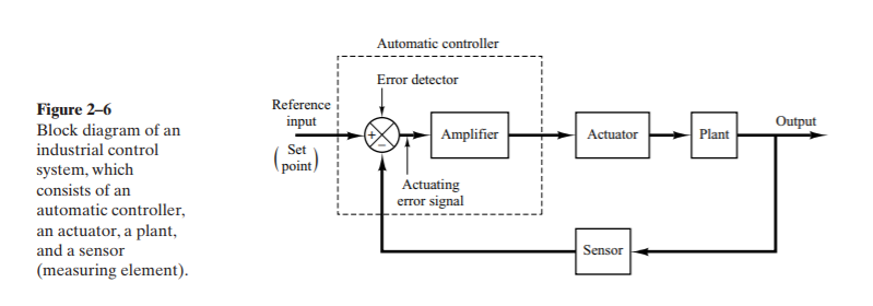
Automatic Controller
An automatic controller compares the actual value of the plant output with the reference input (desired value), determines the deviation, and produces a control signal that will reduce the deviation to zero / a small value.
The components are as follows :
Error Detector
Amplifier
Actuator : The actuator is a power device that produces the input to the plant according to the control signal so that the output signal will approach the reference input signal.
Plant
Sensor
Classification of Industrial Controllers
Two Position / On-Off Controllers
Proportional Controllers
Proportional-plus-Integral Controllers
Proportional-plus-Derivative Controllers
Proportional-plus-Integral-plus-Derivative Controllers
On off Control
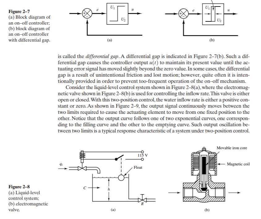
Let the output signal from the controller be u(t) and the actuating error signal be e(t). In two-position control, the signal u(t) remains at either a maximum or minimum value, depending on whether the actuating error signal is positive or negative, so that where U1 and U2 are constants. The minimum value U2 is usually either zero or –U1 .
u(t) = U1, for e(t) > 0
= U2, for e(t) < 0
Eg: Electric Operated Solenoid Valve
Output Characterestic
Output oscillation between two limits is a typical response characteristic of a system under two-position control.
Differential Gap : The range through which the actuating error signal must move before the switching occurs is called the Differential Gap.
Cause : Unintentional Friction / Lost Motion; however quite often it is provided intentionally in order to prevent the too-frequent operation of the on-off mechanism.
Procedures for Drawing a Block Diagram
Write the equations that describe the dynamic behavior of each component.
Take the Laplace transforms of these equations, assuming zero initial conditions, and represent each Laplace-transformed equation individually in block form.
Finally, assemble the elements into a complete block diagram.
Information
- Description
- Note on Control Systems, created by Lingesh K on 25/02/2018.
- Created by
- Lingesh K
- Views
- 1
- Rating