
Fichas
Unit 7 - Cranium and Vertebral Column
Fichas del conjunto (74)
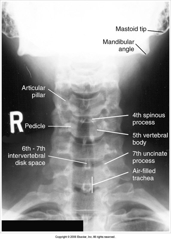
- 1AP axial cervical spine evaluation criteriaC3-C7 visible
no rotation
spinous processes lined up to midsagittal plane (MSP)
SC joints are symmetric and equidistant from spine
mastoid tips are equidistant from spine - 2—chin depressed over C3
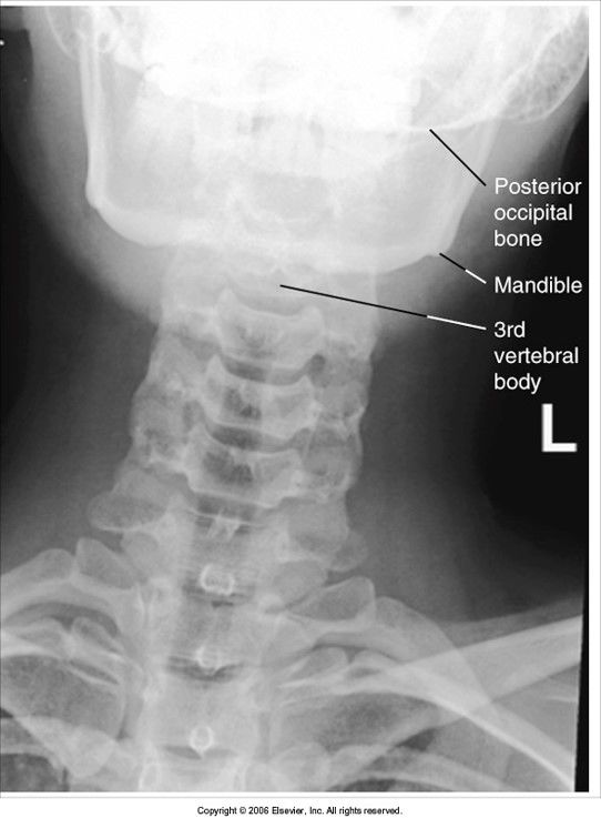
- 3—rotation to the left
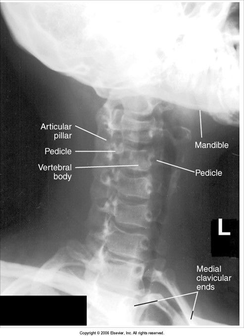
- 4Oblique C-Spine evaluation criteriaRAO and LAO show IVF closest to IR
RPO and LPO show IVF farther from IR
open IVF
pedicles in profile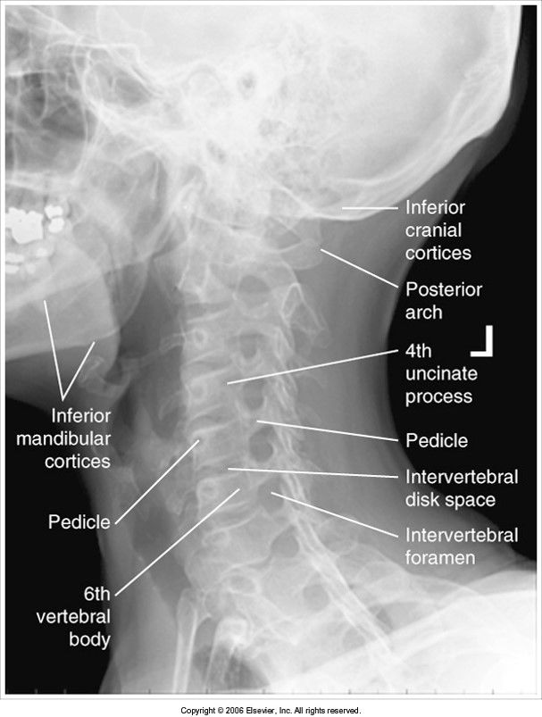
- 5—no cephalic angle
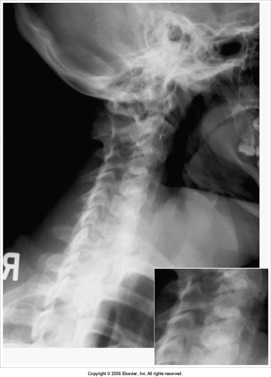
- 6—underrotation
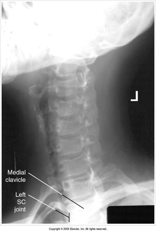
- 7—overrotation
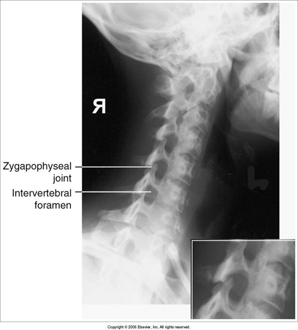
- 8Lateral C-Spine evaluation criteriaall 7 vertebrae are visible
spinous processes in profile
right and left zygapophyseal joints (z. jt.) and articular pillars are superimposed
posterior arch and spinous process of C2 are in profile
intervertebral disk spaces open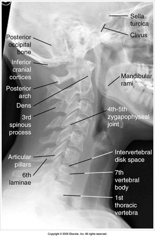
- 9—mandibular rami are not superimposed: pt. rotated
articular pillars and z. jt.s are separated: pt. head tilted away from IR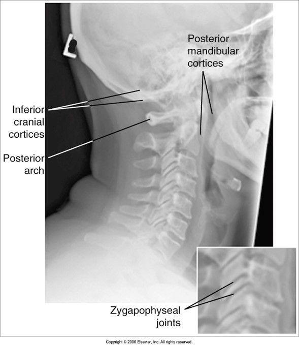
- 10—base of skull and sella turcica coned off
z. jt.s closed: rotation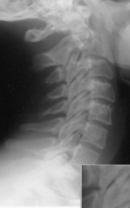
- 11—mandible not superimposed: head is tilted
z. jt.s are separated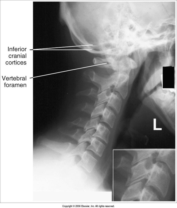
- 12—C7 is invisible behind the shadow of the shoulders - give pt weights to relax shoulders down
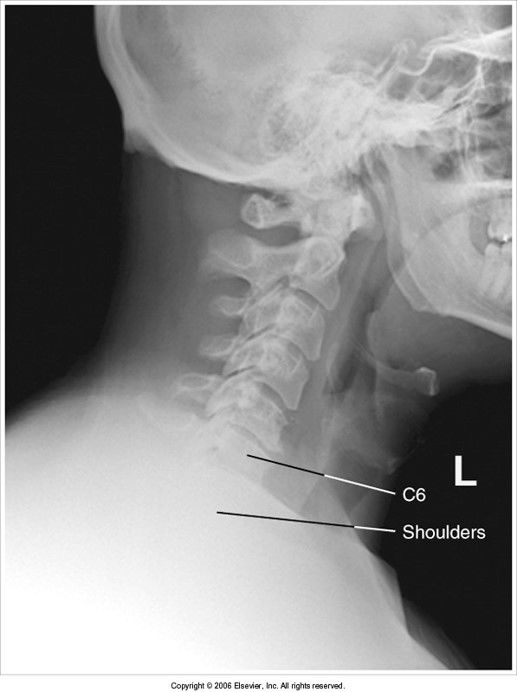
- 13AP Open Mouth evaluation criteriaatlas and axis, ondontoid, lateral masses of C1, and z. jt.s of C1-C2 are well visualized without superimposition
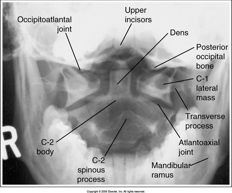
- 14—teeth are superimposed over the dens: head is tilted forward
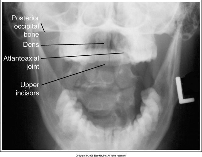
- 15—base of the skull superimposes the dens: head is extended too far
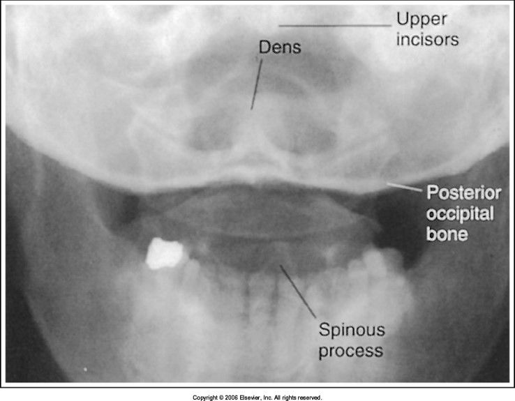
- 16—dens is situated to the left of the MSP: pt's head is rotated towards the right
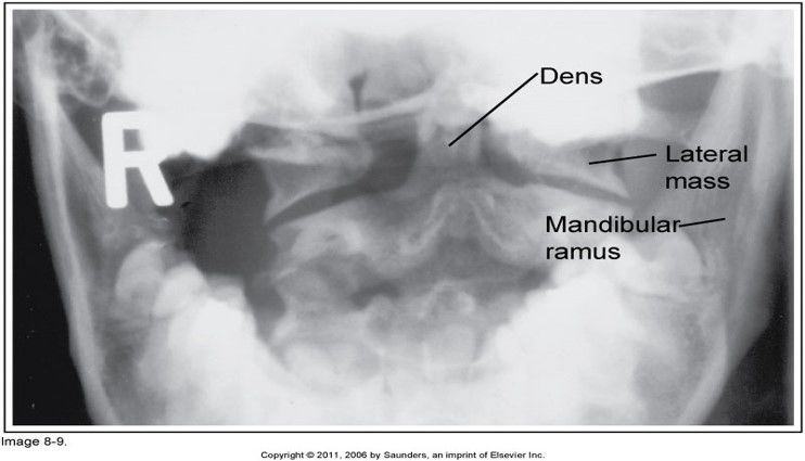
- 17AP Thoracic Spine evaluation criteriaall 12 thoracic vertebrae are visible with no rotation, flexion, extension, or tilt
collimation is evident
exposure is taken after expiration to reduce lung volume and create more uniform density
patient positioned so the thorax is under the cathode side of the beam (annode-heel effect)*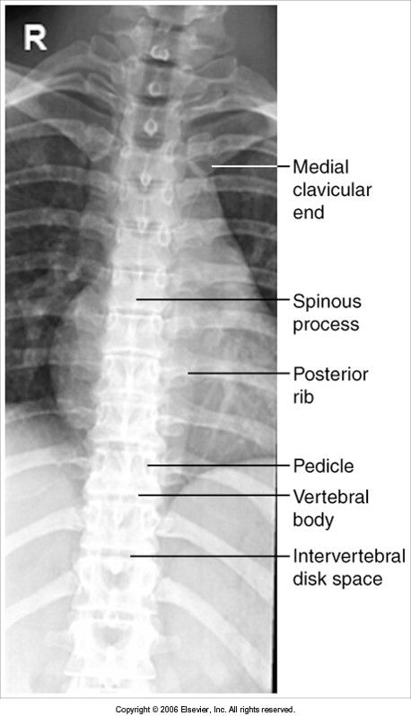
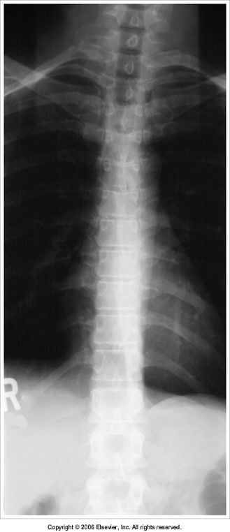
- 18—exposure was taken on full inspiration: lung fields are overexposed and density is not well distributed
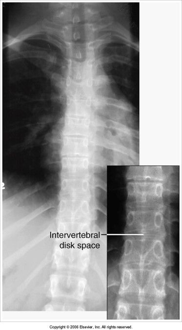
- 19—intervertebral joint spaces are obscured: pt's legs/knees were extended when they should've been flexed
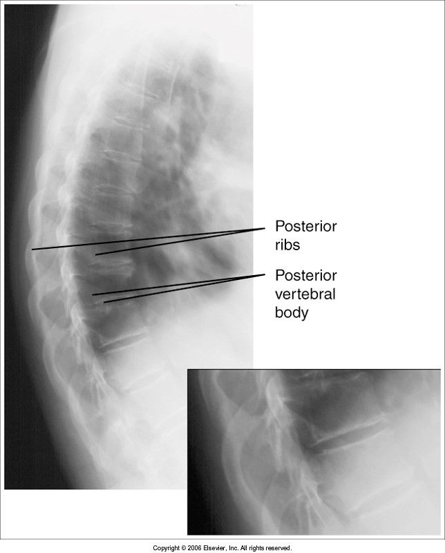
- 20Lateral T-Spine Evaluation Criteriathoracic bodies of T4-T12 are seen with open IVF and no rotation
*exposure taken using a breathing technique to blur out the ribs and lung markings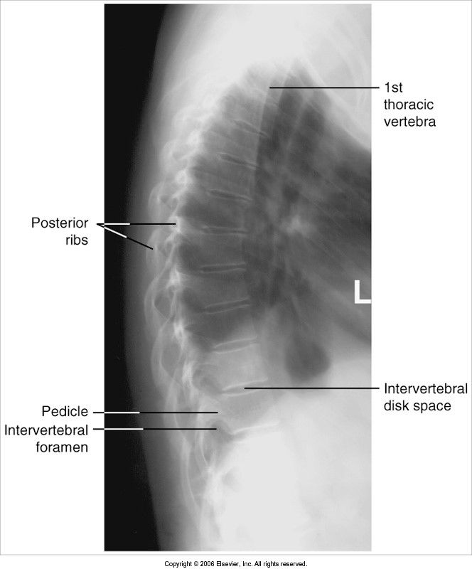
- 21—ribs are not blurred out: inadequate breathing technique
lower thoracic vertebral bodies are obscured: pt's hips were not supported so spine is curved laterally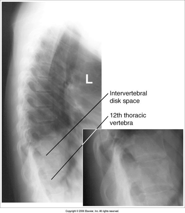
- 22—posterior ribs and vertebral bodies aren't superimposed: pt rotated
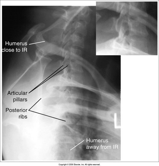
- 23Swimmer's Lateral T-Spine Evaluation CriteriaC5-T3 included
humerus should be above head and aligned with vertebral column
humerus away from IR should be anterior to spine
intervertebral disk spaces should be open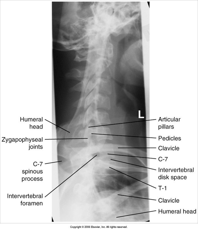
- 24—acceptable
(bontrager's demonstration picture)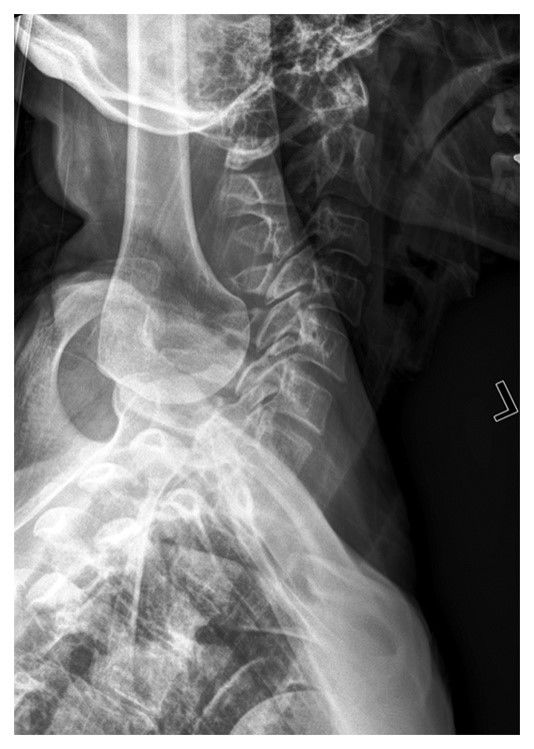
- 25—posterior ribs and vertebral bodies aren't superimposed: patient is rotated
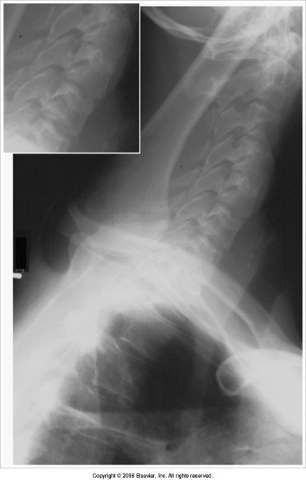
- 26—intervertebral disk spaces closed: c-spine is not parallel to IR
- 27AP Lumbar evaluation criteriaT12-sacrum are included
intervertebral disk spaces are opened
patient positioned with knees and hips flexed
sacrum/coccyx centered to MSP and pelvic inlet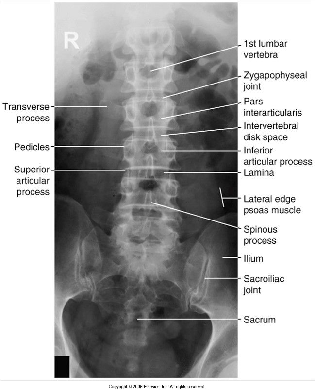
- 28—spinous processes are shifted to the right of the midline and the sacrum/coccyx shifted to the right of MSP: patient's hips rotated towards the left
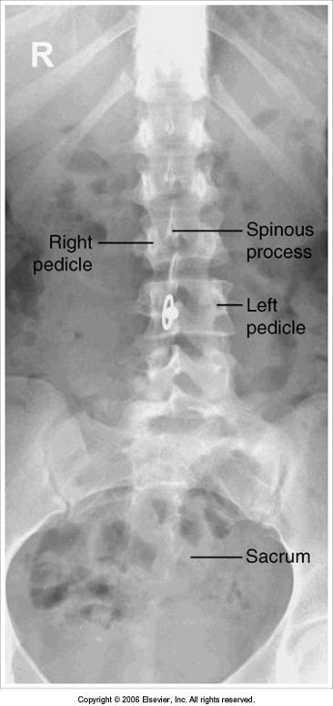
- 29extreme scoliosisslight scoliosis
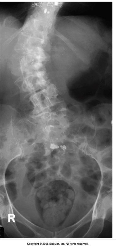
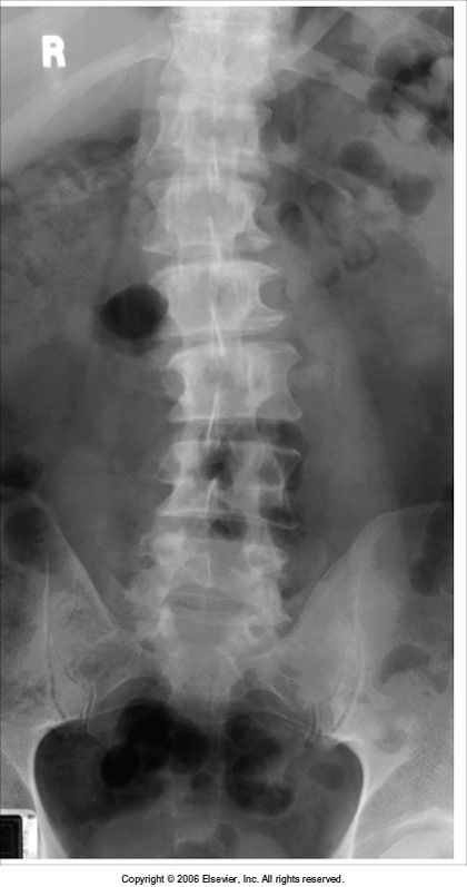
- 30—intervertebral disk spaces are closed: the knees and hips need to be flexed
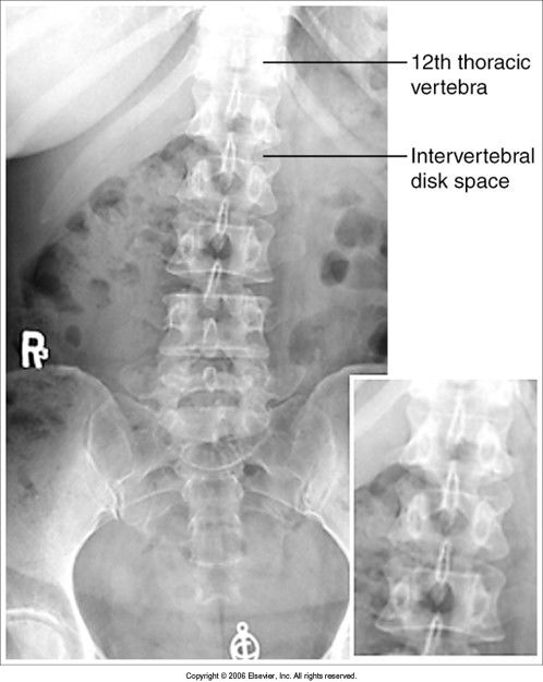
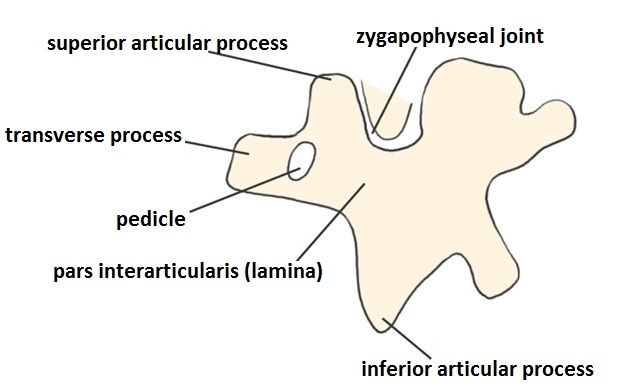
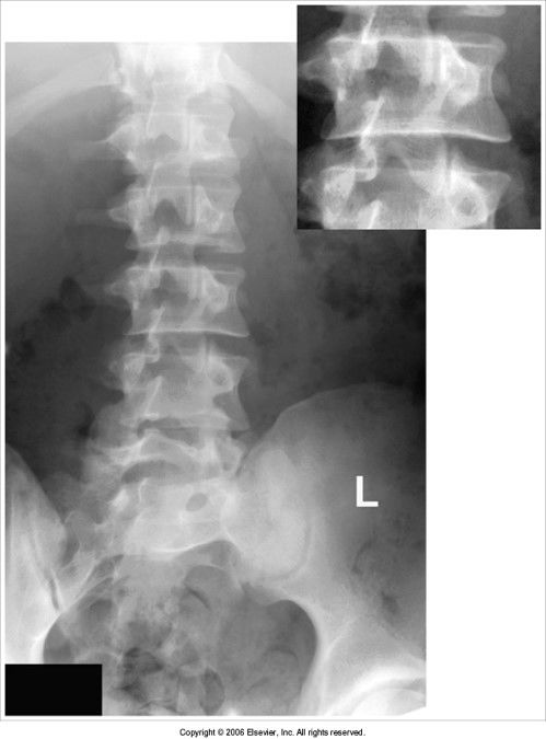
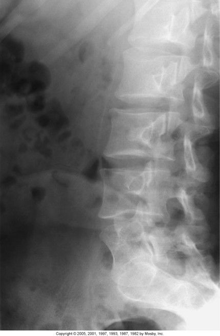
- 31Oblique Lumbar evaluation criteriascotty dogs should be visible
open z. jts
LPO and RPO show the z jt closest to IR
LAO and RAO show the z jt farther from IR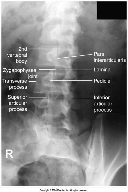
- 32—Scottie Dog
- 33—underrotation
- 34—overrotation
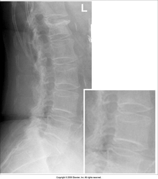
- 35Lateral Lumbar evaluation criteriaopen intervertebral foramina (IVF)
open intervertebral disk spaces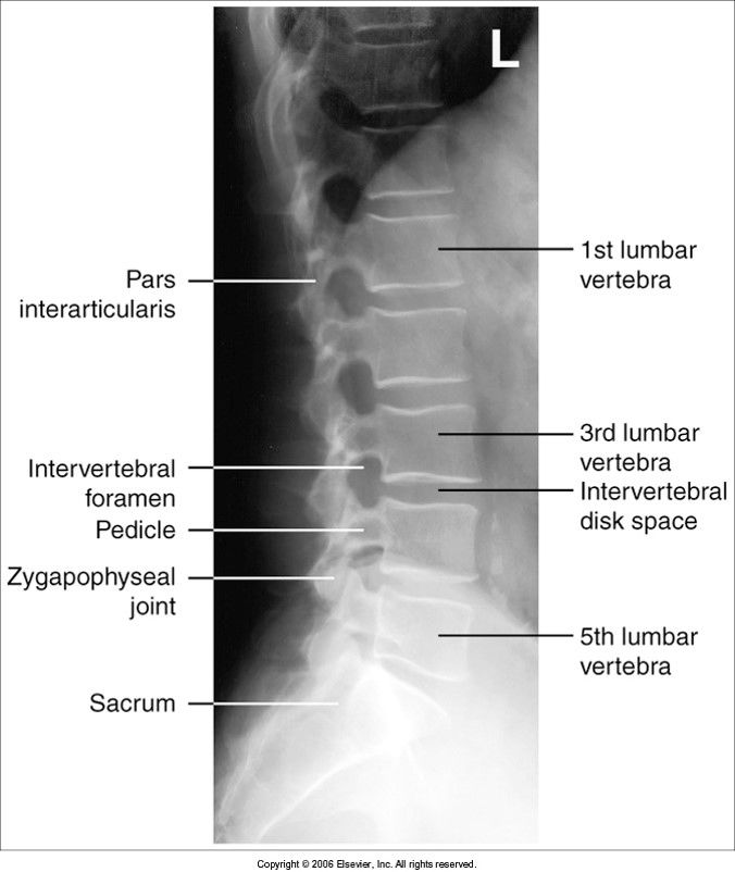
- 36—intervertebral disk spaces closed - hips/waist was not supported
- 37L5-S1 spot evaluation criterialumbosacral joint open
IVF clearly demonstrated
right/left pedicles superimposed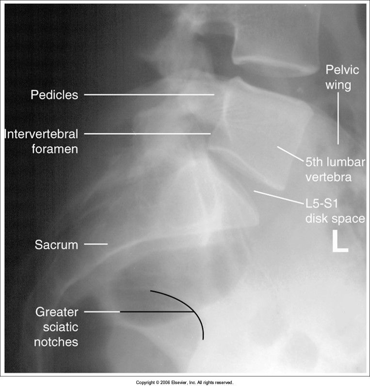
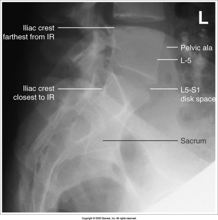
- 38—iliac wings are not superimposed - pelvis is tilted from being unsupported
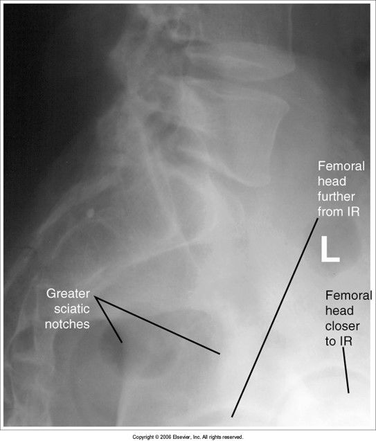
- 39—femoral heads aren't superimposed: pelvis is rotated
- 40PA Skull 0 degrees evaluation criteriapetrous ridges fill the orbits
orbits are symmetric and equidistant from MSP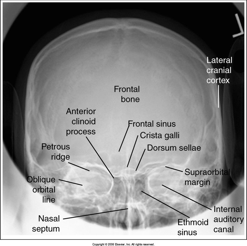
- 41—petrous ridges aren't filling the orbits
chin isn't tucked enough to get OML perpendicular to IR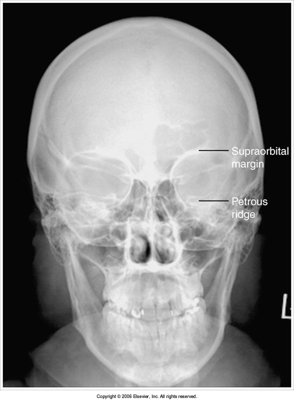
- 42—petrous ridges are seen above the orbital rims
chin is tucked too much - OML isn't perpendicular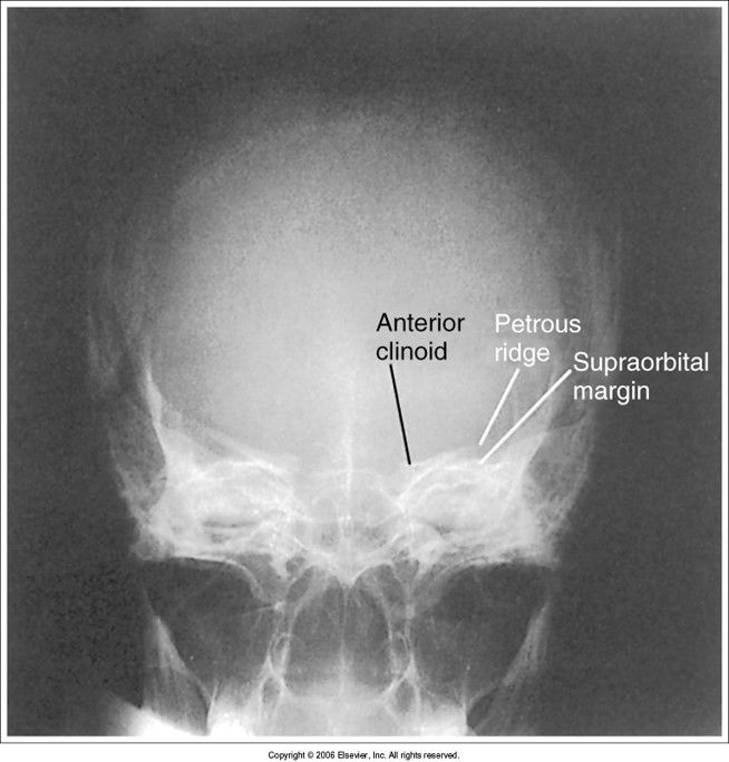
- 43PA Caldwell 15 evaluation criteriapetrous ridges are seen within lower 1/3 of orbits
OML is perpendicular to IR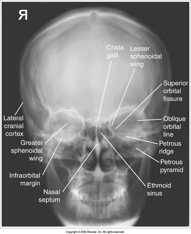
- 44—CR angle was 15 cephalic: orbits are magnified, skull is foreshortened
*in trauma cases this is acceptable*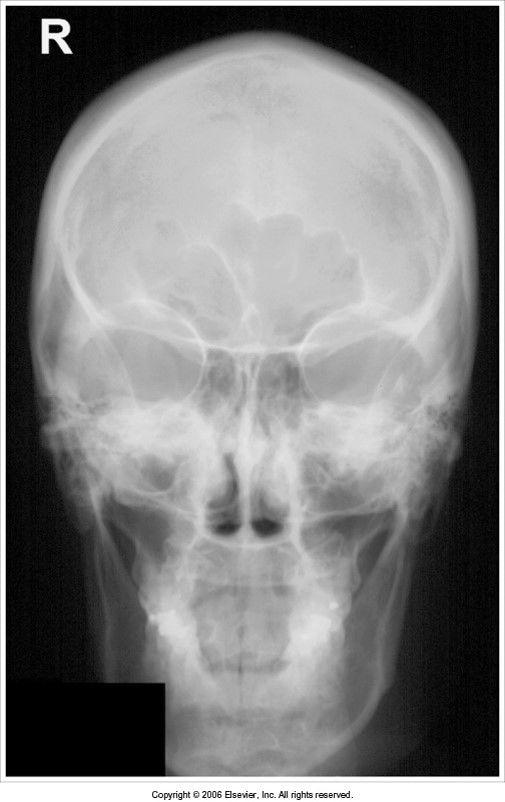
- 45—head is tilted
petrous ridges are below orbital floors: CR was angled too caudal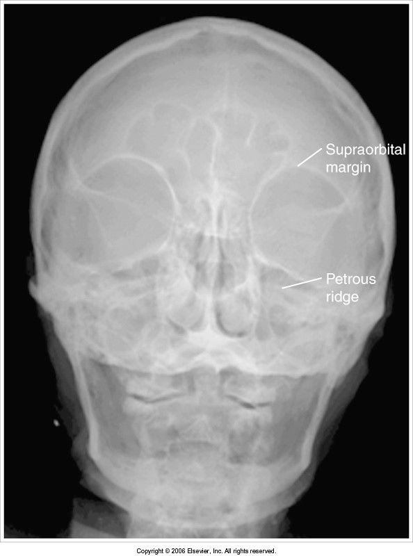
- 46AP Axial Towne Method evaluation criteriadorsum sellae is seen within the foramen magnum
petrous pyramids are symmetric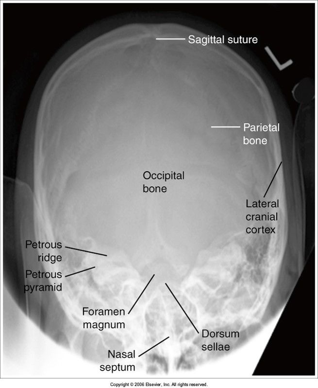
- 47—dorsum sellae is off center to the right: patient's face is turned to the left
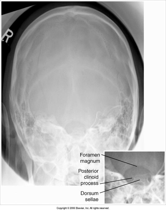
- 48—dorsum sellae is not within foramen magnum
head is not flexed enough OR we need more tube angle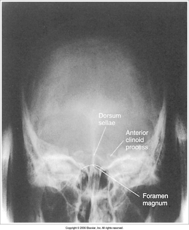
- 49—posterior arch of C1 is seen within foramen magnum: head is over flexed, OR the tube angle is too caudal
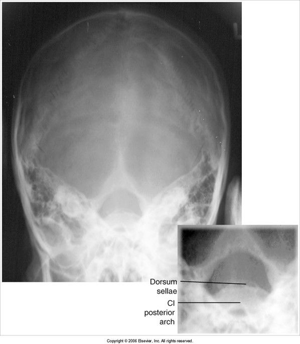
- 50Lateral Skull evaluation criteriasuperimposed facial bones
sella turcica and clivus are in profile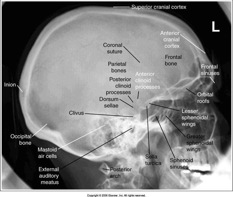
- 51—structures aren't superimposed vertically
TILT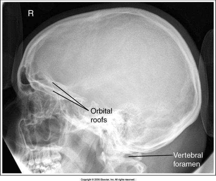
- 52—facial features aren't superimposed horizontally
ROTATION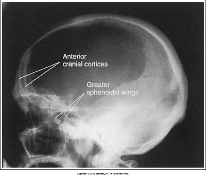
- 53Parietoacanthial Waters Modified and Transoral evaluation criteriaPETROUS RIDGES ARE BELOW THE MAXILLARY SINUSES
facial features and sinuses are symmetric
no rotation
SPHENOID sinus is best viewed on the transoral projection
MML or LML perpendicular to IR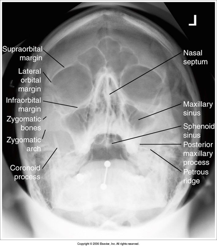
- 54—since this is a modified waters view, it's okay that the petrous ridges are within the maxillary sinuses
*acceptable image*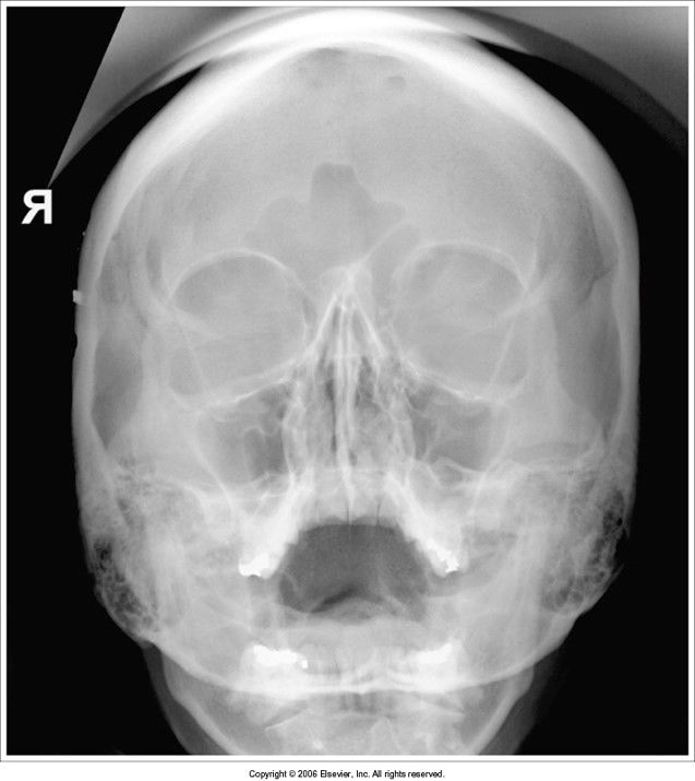
- 55—standard PA waters:
-petrous ridges are within the maxillary sinuses: MML is not perpendicular to IR
-head must be extended backward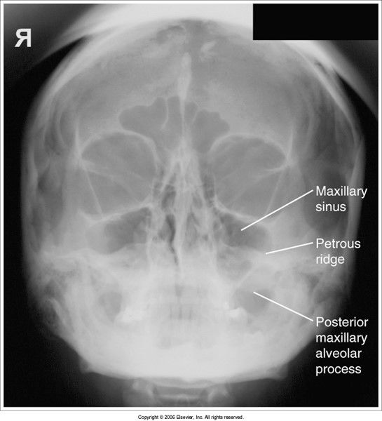
- 56—transoral waters:
petrous ridges are low, and upper teeth are in maxillary sinuses
head is overextended - flex head forward to bring MML perpendicular to IR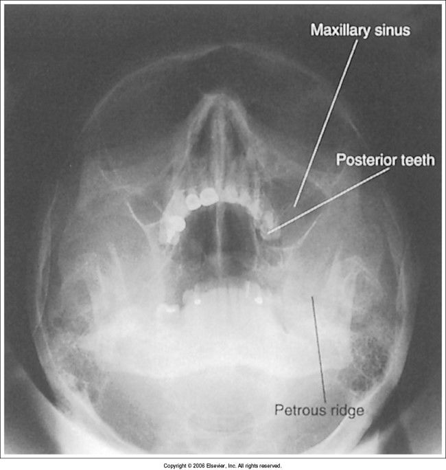
- 57if a patient is rotated with the right side more anterior on the AP C-spine, which SC joint will be lying more over the spine?Right SC joint
*side closest to IR will be open* - 58Which positioning line is used to position the head for the AP c-spine?AML
- 59On this oblique of the c-spine you will see the IVF closest to the IRRAO/LAO
- 60On this oblique of the l-spine, you will see the zygapophyseal joints of the side closest to the IRRPO/LPO
- 61On this view of the t-spine you will see the zygapophyseal jointsLateral
- 62On this oblique of the l-spine, you will see the zygapophyseal joints on the side farthest from the IRRAO/LAO
- 63On this oblique of the c-spine you will see the IVF farthest from the IRRPO/LPO
- 64Which direction will you angle the CR for an AP oblique c-spine?15-20 cephalic
- 65Which direction will you angle the CR for a PA oblique c-spine?15-20 caudal
- 66For an oblique c-spine, the _________ obliques provide less absorbed dose to the thyroid glandanterior
- 67how can you determine if there was a tube angle on an oblique c-spine projection?the disc spaces will be open but the IVF will be closed
- 68On a lateral c-spine, if the head is tilted towards the IR we will see the ....vertebral foramen of C1
- 69On a lateral c-spine, if the head is tilted away from the IR, we will see .....posterior arch of C1 still in profile, but the rami of the mandible are not superimposed and the base of the skull
- 70On the AP open mouth projection of the c-spine, the teeth are superimposing the dens. How do we correct this problem on the repeat image?extend head back
- 71On the AP open mouth projection of the c-spine, the base of the skull is superimposing the dens. What will we do on the repeat?flex head forward
- 72how can you determine which side was rotated more anteriorly on a lateral lumbar/lateral L5-S1?the femoral heads should be superimposed.
The side that is farther from the IR will be more magnified
if the magnified femoral head is more anterior, the patient is rotated - 73There's trauma and you need to do a PA Caldwell skull projection. You can't get the OML perpendicular to the IR because of the C-collar. What will you do?angle your CR perpendicular to the OML, (caudal if PA, cephalic if AP)
then add an additional 7 degrees to the tube angle - 74—
Información
- Descripción
- ARRT Image Evaluation Fichas sobre Unit 7 - Cranium and Vertebral Column, creado por RadTech Fairy el 11/04/2017.
- Creado por
- RadTech Fairy
- Visitas
- 2.543
- Valoración